Fine-tuning for XY Calibration
Fine-tuning is usually performed at two Scan size settings: 150 V and 440 V. Both horizontal and
vertical measurements of sample features are made, then compared with actual distances. Based
upon this comparison, computer parameters are fine-tuned. To fine-tune your SPM for maximum
XY measuring accuracy, review the procedure below.
Prepare System for Fine-tuning
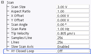
- Set the Scan Size parameter on the Scan Controls panel to the maximum value (440 V).
- Verify that the Scan Angle is set to 0.00 degrees.
- In the Scan view, set XY Closed Loop to Off for open loop scanning (this option is available in the Expanded mode).
- Mount a calibration reference in the SPM and begin imaging. This may consist of a generic
(e.g., 10 micrometer, silicon) reference, or a sample having features of known dimensions (e.g.,
grating, etc.).
- Optimize the image quality.
NOTE: Your calibration and fine-tuning procedures are no better than the procedures
and references used. Choose both carefully.
Measure Horizontally at 440 V Scan Size
- Set the Scan size parameter on the Scan panel to the maximum value (440 V).
- Verify that the Scan angle is set to 0.00 degrees.
- Engage the tip on the sample surface.
NOTE: Contact AFM mode is preferred for this procedure because the scan rate is faster
for Contact mode than tapping mode.
- After you have completed a scan pass, click Calibrate > Scanner > XY. The Scanner
Calibration dialog box displays:
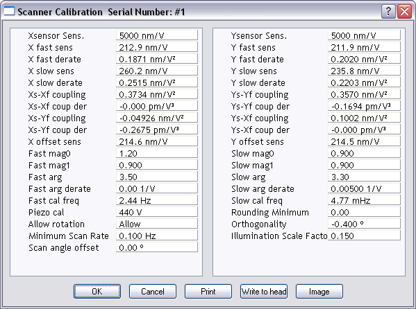
- Click Image.
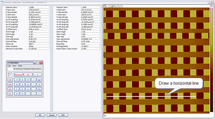
- Select two widely-spaced features on the sample image of known separation and draw a horizontal line between them (for example, on a 10 μm silicon
reference, draw the line from the left side of one pit to the left side of another pit as far away
as possible). The screen will display the measured distance between pits next to the line:
- Verify that the microscope’s measured distance agrees with the known horizontal distance. If
there is significant disagreement between the two, fine tuning is required; go to the next step.
If the displayed distance agrees with the known distance, skip to Measure Vertically at
440 V Scan Size.
- Based upon the results in the above step, divide the known distance by the distance displayed
next to the line drawn a few steps earlier:

- Multiply the quotient obtained above by the X fast sens value shown on the Scanner
Calibration panel.
- Enter the new value. The new value adjusts the scanner’s fast axis to more closely match
calculated distances with actual feature distances. The new sensitivity setting takes effect as
soon as it is entered.
- Repeat Step 6 to check your change.
- To save new values to the computer’s hard disk, click OK. This closes the Scanner
Calibration panel.
Measure Vertically at 440 V Scan Size
- Return to the image of the calibration reference.
- Select the Calibrate > Scanner > XY function to display the Scanner Calibration
dialog box.
- Click Image to view the image while in the Scanner Calibration window.
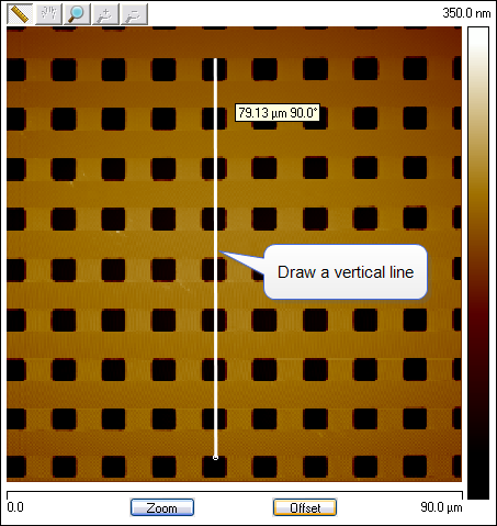
- Wait for at least three full scans to allow the piezo to stabilize then select two widely spaced
features and then draw a vertical line connecting like portions of features (top edge-to-top
edge, etc.). The SPM displays the calculated distance between features:
- Verify that the microscope’s calculated distance agrees with the known vertical distance. If
there is significant disagreement between the two, fine tuning is required; go to the next step.
If the displayed distance agrees with the known distance, skip to Measure Horizontally at
150 V Scan Size.
- Using the results from the above step, divide the known distance by the distance displayed
next to the line drawn a few steps earlier.
- Select the Y slow sens parameter.
- Multiply the quotient obtained earlier by the Y Slow Sens value shown on the Scanner
Calibration dialog box.
- Enter the new value to adjust the scanner’s slow axis to more closely match calculated
distances with actual feature distances.
- To save the new parameter value, click OK.
- Repeat step 4 to check your change.
Measure Horizontally at 150 V Scan Size
- Verify that the Scan angle is set to 0.00 degrees, and that Units (Other panel) is set to Volts.
- Set the Scan size parameter on the Scan panel to one-third the maximum (150 V).
- Select two widely-spaced features on the sample image of known separation, then use the
mouse to draw a horizontal line between them.
NOTE: For example, on a 10 μm, silicon reference, draw the line from the left side of
one pit to the left side of another pit as far away as possible. The microscope
displays the measured distance next to the line.
- Verify that the microscope’s measured distance agrees with the known horizontal distance.
- If there is significant disagreement between the two, fine-tuning is required; go to the next
step. If the displayed distance agrees with the known distance, skip to Measure Vertically at
150 V Scan Size.
- Perform fine-tuning adjustments using either trial and error or calculate the precise correction
(see Calculation Method).
Trial and Error Method
- Select the Calibrate > Scanner > X-Y function to display the Scanner Calibration
dialog box.
- Click Image to make a measurement while in the Scanner Calibration window.
- Select the X fast derate parameter or Y slow derate for Y-axis adjustment.
- If the measured distance is less than the actual distance, decrease the X fast derate parameter
slightly or Y slow derate for Y-axis adjustment and re-measure image features.
- Adjust deratings up or down until measurements accord with known feature distances.
Calculation Method
- Select Calibrate > Scanner > X-Y to display the Scanner Calibration dialog box.
- Click Image to make a measurement while in the Scanner Calibration window.
- Record the X fast derate or Y slow derate value.
- Perform the following calculation:
- Where:
- s is the X Fast Sens or Y Slow Sens value
- a is the actual distance
- d is the X Fast Derate or Y Slow Derate value you recorded in the above step
- m is the measured distance
- v is the Scan Size in volts
- Return to the Scanner Calibration dialog box.
- Enter the new X Fast Derate value calculated in Step 4. This adjusts the scanner’s fast axis
to more closely match calculated distances with actual feature distances.
- To set the new parameter value, click OK.
- Measure horizontally again to verify that the measurement is now in agreement with the
known distance.
Measure Vertically at 150 V Scan Size
- Select two widely-spaced features on the sample image of known separation.
- Use the mouse to draw a vertical line between them.
NOTE: For example, on a 10 μm, silicon reference, draw the line from the top edge of
one pit to the top edge of another pit as far away as possible. The microscope
displays the measured distance next to the line.
- Verify that the microscope’s measured distance agrees with the known vertical distance. If
there is significant disagreement between the two, execute the fine tuning procedure; go to
the next step. If the displayed distance agrees with the known distance, no further calibration
is required.
- Adjust the Yslow derate value by using one of two methods: 1) the Trial and Error Method
or 2) theCalculation Method
described above.
Change Scan angle and Repeat Calibration Routines
- Change the Scan angle on the Scan Controls panel to 90º.
- Repeat steps above for the following parameters: Y Fast Sens, X Slow Sens, Y Fast
Der, AND X Slow Der to ensure the scanner is calibrated properly along the X- and Yaxis
for scanning at 90º.
| www.bruker.com
|
Bruker Corporation |
| www.brukerafmprobes.com
|
112 Robin Hill Rd. |
| nanoscaleworld.bruker-axs.com/nanoscaleworld/
|
Santa Barbara, CA 93117 |
| |
|
| |
Customer Support: (800) 873-9750 |
| |
Copyright 2010, 2011. All Rights Reserved. |
Open topic with navigation
